Reverberation Chamber Mini-Class
Q1. What is a reverberation chamber?
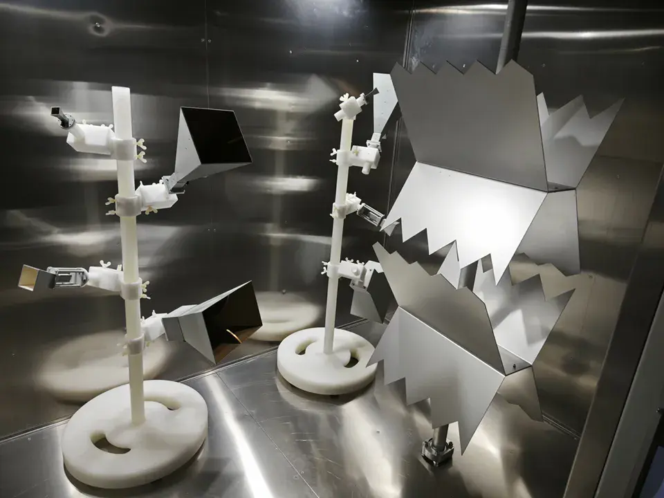
The term "reverberation chamber" is used in both the acoustic and electromagnetic fields, and the term in the electromagnetic field actually originates from the acoustic field. An acoustic reverberationchamber is a laboratory where all sound energy is reflected at all boundaries and fully diffused, creating a diffuse field with uniform energy density everywhere and random distribution in all propagationdirections. An electromagnetic reverberation chamber is a shielded cavity with electrically large size and high-conductivity reflective walls. The commonly used reverberation chamber is of the mechanical stirring type, which is usually equipped with one or several mechanical stirrers or tuners. By rotating the stirrers, the boundary conditions of the chamber are changed, thereby forming an electromagneticenvironment with statistically uniform, isotropic and randomly polarized properties inside the chamber.
Q2. Why is a reverberation chamber needed?
The electromagnetic reverberation chamber is a new technology and platform for electromagnetic compatibility (EMC) testing proposed after the anechoic chamber, Gigahertz Transverse Electromagnetic(GTEM) cell, and open test site. In some EMC tests, the anechoic chamber method is gradually being replaced by the reverberation chamber method. For example, in electromagnetic immunity testing, the reverberation chamber method has prominent advantages over the anechoic chamber method in the following three aspects: Compared with the anechoic chamber scheme, the reverberation chamber significantly improves the testing efficiency (the specific improvement degree is affected by factors such as the stirring step length and the size of the device under test). The traditional anechoic chamber method requires the antenna to test in both horizontal and vertical polarization directions, and also cover as much space as possible. Therefore, it is necessary to adjust the polarization (2 polarizations) and position (n heights) of the source antenna multiple times, requiring 2n tests, and the test results can only be obtained after further data analysis and processing. In contrast, the reverberation chamber scheme only requires the stirrer to rotate one full circle (with a rotation step of m degrees), and only 360/m tests are needed to obtain reliable test results. Compared with the anechoic chamber scheme, the construction cost of the reverberation chamber is reduced by about 4 times, making it more suitable for high-field strength testing. Due to the high quality factor of the reverberation chamber and the continuous reflection and superposition of electromagnetic waves between the radio frequency shielding walls to the maximum, the reverberation chamber can generate a high field strength in the entire test
area with a small transmission power, easily achieving a test field strength of 200V/m or higher. In contrast, the anechoic chamber needs high-gain antennas and high-power amplifiers to achieve a large field strength in a small test area, and the high cost of high-power amplifiers makes the overall construction cost of the anechoic chamber more than 4 times that of the reverberation chamber. The reverberation chamber has higher testing accuracy than the anechoic chamber scheme. Even though the anechoic chamber testing scheme considers both horizontal and vertical polarization directions and the height of the transmitting antenna, the actual implementation is still a discrete spatial distribution. At the same time, because the direction pattern of a specific device under test may not be perpendicular to its surface, the test is not comprehensive. Since the electromagnetic waves in the anechoic chamber are plane sources, the field strength is more uneven when testing large-sized objects. In the reverberation chamber scheme, the field polarization information in the test area is richer, and the field in the entire test area is uniformly distributed, creating an immersive continuous field area for the device under test. Therefore, the test results of the reverberation chamber method are more reliable than those of the anechoic chamber method.
Q3. What are the differences among reverberation chambers, anechoic chambers, and shielded rooms?
|
Test Environment
|
Reverberation Chamber
|
Anechoic Chamber
|
Shielded Chamber
|
|
One-sentence Description
|
The walls are metal shielding walls, achieving strong reflection of electromagnetic waves. Meanwhile, there are stirrers, so that the test area obtains a uniform field distribution; a small transmission power can achieve a large field strength
|
The walls are covered with absorbing materials, simulating an open field, and realizing an ultra-low reflection environment for electromagnetic waves
|
Usually, the walls, floor, and ceiling have good shielding materials. Mainly used to shield external electromagnetic interference and ensure that the test area is not affected by external electromagnetic waves.
|
|
Design and Structure
|
- Six-sided all-metal strong reflection shielding walls - Equipped with stirrers or resonators
|
- All walls are made of absorbing materials
|
- Six-sided all-metal shielding walls - No stirrers
|
|
Electromagnetic Characteristics
|
- A highly reflective environment, simulating multi-path propagation conditions through reflection and scattering - The field in the test area is uniformly distributed
|
- Simulate an open space, a low-reflection electromagnetic environment, reducing signal reflection to obtain accurate radiation characteristics
|
- Shield external electromagnetic wave interference, and the internal environment is controlled to ensure test accuracy
|
|
Main Uses
|
- Evaluate the performance of equipment in complex electromagnetic environments, especially electromagnetic compatibility testing under multi-path propagation conditions - More suitable for high-field strength testing - Particularly suitable for electromagnetic compatibility testing of large equipment levels
|
- Measure and test the radiation characteristics and performance of microwave equipment (such as antennas, radar systems, etc.), especially when high-precision directivity and frequency response tests are required.
|
- Shield external electromagnetic interference
|
|
Maintenance and Cost
|
Maintenance: Need to maintain the stability and integrity of the reflector, regular cleaning and inspection. Cost: Generally, the design and construction are complex.
|
Maintenance: Need to regularly inspect and replace wave-absorbing materials to maintain wave-absorbing performance. Cost: Relatively high, the design of absorbing materials and structures is complex.
|
Maintenance: Mainly maintain the integrity of shielding materials and structures to prevent electromagnetic leakage. Cost: Relatively low, involving high-quality shielding materials and structures.
|
Q4. What fields and scenarios is a reverberation chamber suitable for?
Reverberation chambers are playing an increasingly crucial role in electromagnetic compatibility (EMC) testing and equipment performance evaluation. Especially as more and more products adopt complex high-frequency radiation patterns, the repeatability of EMI (Electromagnetic Interference) measurement using the existing open test site and anechoic chamber methods will be very low, and the reverberation chamber will become the preferred test environment. It has a wide range of applicable fields, from communications, new energy vehicles, automotive electronics, consumer electronics to military aerospace and medical equipment, and the reverberation chamber plays a vital role. By using a reverberation chamber for detailed electromagnetic testing, the reliability and compliance of equipment in various electromagnetic environments can be ensured, meeting strict international standards and market demands.
Applicable Fields
1. Communication systems:
Test the performance of wireless communication devices (such as mobile phones, wireless network devices) in complex electromagnetic environments, including signal transmission, reception capabilities, and anti-interference performance.
2. New energy vehicles and automotive electronics:
Evaluate the performance of automotive electronic devices (such as vehicle-mounted radars, vehicle-mounted communication systems) in multi-path environments to ensure their reliability and safety in actual driving conditions. It will show more obvious advantages in the electromagnetic compatibility design and testing of the whole vehicle, and can be used in complex electromagnetic environments, the shielding effectiveness of high-voltage systems of new energy vehicles, vehicle immunity testing, etc.
3. Consumer electronics:
Test the radiation characteristics of various consumer electronic products (such as televisions, audio equipment) in multi-path environments to ensure that the products meet the EMC standards in the market.
4. Military and aerospace:
In the military and aerospace fields, reverberation chambers are used to evaluate the electromagnetic compatibility of high-frequency equipment such as military communication devices and radar systems, ensuring their reliability and effectiveness in extreme environments, and are especially suitable for EMC testing of large equipment levels.
5. Medical equipment:
Conduct electromagnetic compatibility testing on medical equipment (such as imaging equipment, monitoring instruments) to ensure their safety and performance stability in medical environments.
Test Scenarios Interference immunity testing:
Evaluate the anti-interference ability of equipment in multi-path environments and test its performance under various interference signal conditions.
Radiated emission testing: Conduct radiated emission testing of equipment in the reverberation chamber to evaluate its radiation intensity and directionality under different reflection conditions.
System-level testing: Test the entire system to check the comprehensive performance of all components in the system under complex electromagnetic environments, including mutual interference between devices and signal transmission quality.
Standard compliance testing: Conduct testing in accordance with international and national standards to verify whether the equipment meets the relevant electromagnetic compatibility requirements.
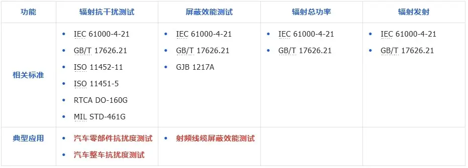
Relevant Standards:
Q5. What indicators should be considered when building a reverberation chamber?
A reverberation chamber system is complex and precise, with a plethora of introductions about its indicators and functions. Are you struggling, tangled, and anxious about how to make a choice? Worried that the construction plan can meet the testing requirements? Concerned whether the selected plan is optimal? Anxious if the limited funds are spent where most needed? Fret not... Next, starting from the technical core of the reverberation chamber, we'll teach you how to grasp the most core elements, make quick decisions, and choose the most scientific option.
Reverberation Chamber User Requirement Analysis Table
Step 1: Clearly define and quantify your testing needs, including frequency requirements, field strength requirements, and the size of the effective testing area.
Step 2: Clarify the situation of the construction site at your disposal, including detailed dimension information.
Step 3: Determine the overall budget.
Step 4: Check if the testing instruments are already available. If there is no matching equipment, consider if there is a need for domestic instruments and if there are special high-precision requirements.
Step 5: Consider if the subsequent testing items are rather variable and if high-frequency calibrations are needed.
Step 6: Based on the budget and testing requirements, formulate the testing instrument and probe plan.
Key Technical Indicators of Reverberation Chambers
Indicator 1: Field Uniformity in the Testing Area. Company A claims about 2 dB, and Company B about 2.5 dB. How to choose? Don't worry too much. The standard for reverberation chambers clearly stipulates that the field uniformity in the testing area should be 4 dB at low frequencies and 3 dB at high frequencies to meet the requirements. In addition, the field uniformity is comprehensively affected by multiple factors such as "stirrer rotation step length", "testing area range", "source antenna position and angle". There may be significant differences in the premises of test results among different companies. Therefore, there's no need to get hung up on specific values; as long as it meets the standard, it's fine. From the user's perspective, you can consider more about under what testing settings the testing standard can be met!
Indicator 2: Choice of Field Strength. Company A can reach 200 V/m, and Company B can reach 100 V/m. Is A definitely better than B? Obviously not. The maximum field strength in the testing area is strongly affected by multiple factors such as "signal source transmission power", "power amplifier saturation power", "antenna gain", "RF link loss", and "reverberation chamber system reflection loss". Users should clarify their maximum field strength requirements and find the most suitable solution at the lowest cost. Even if there are higher requirements later, this performance can be further improved through the optimization of the above factors. The only factor that cannot be changed later is the "reverberation chamber system reflection loss", so this indicator also reflects the technical level of the reverberation chamber manufacturer.
Indicator 3: Stirrer Shape and Stirring Scheme. There are various claims, but which is better? Theoretically, the larger the stirrer, the better, but it's necessary to consider the reduction of the effective testing area caused by the increase of the stirrer. The final impact needs to be measured by the proportion of the effective testing area and the field uniformity. For the stirrer, on the basis of realizing its functions, the most important thing is to consider its structural stability, which can remain stable during the testing process, not easy to vibrate, and can brake quickly. It helps to improve the testing speed and result stability.
Indicator 4: Testing Efficiency. Testing efficiency is a very crucial indicator, directly determining the testing speed of the system. For example, the larger the stirrer rotation step length, the higher the testing efficiency, but theoretically, the worse the field uniformity. Therefore, how to achieve the required field uniformity for testing under the optimal step length reflects the overall testing level of the reverberation chamber.
Indicator 5: Calibration Efficiency and How to Choose Probes? First of all, standard probes must be selected for the probes, and the probe accuracy determines the testing accuracy of the reverberation chamber to a certain extent. Calibrating a reverberation chamber is usually a major project. For a single-probe scheme, the calibration process may even take 2 - 3 days, resulting in the calibration of the reverberation chamber not being carried out one by one with the testing items. Usually, monthly calibration is adopted. Therefore, the calibration efficiency of the reverberation chamber is also a key reference. The calibration efficiency is closely related to the overall scheme level of the reverberation chamber. At the same time, if the budget is sufficient, using an array of multiple probes can significantly linearly improve the calibration efficiency. However, standard probes are generally expensive, so a balance between the expected efficiency and the budget cost needs to be found.
Indicator 6: Software Control System. It is like the blood of the entire testing system. With a good hardware foundation, the software control system directly determines the testing efficiency, testing convenience, and user experience. Therefore, intelligence, friendly human-computer interaction, and subsequent updates and iterations are crucial.
Shenzhen Sai Sheng Technology Co., Ltd. specialize in:RF shield box、acoustic chamber、automatic test connectors、antenna coupler……